How to Quickly Enhance 3D Views in Revit

One of the major benefits of Revit is that it is inherently a three-dimensional approach to drafting which means a user should be able to quickly and efficiently produce three-dimensional drawings for a wide range of purposes including:
Helping a client visual a space or building | Coordinating design with consultants | Identifying potential construction or detailing issues early on
Part of this process involves accurate modeling of information; the other part involves actively “thinking” in 3D. Three-dimensional views should be referred to often while working in Revit. It allows you to visualize the model outside of a flat 2D view such as a plan or elevation. The issue is that Revit often seems to make 3D inherently cumbersome or visually unattractive.
By default, Revit lacks the napkin-sketch appeal of Sketch Up and the glossy polish of a 3DS Max rendering. Revit itself has been upgraded massively over the years in terms of its built-in rendering engine, so it is now possible to create presentation quality renderings. Autodesk has also recently introduced Showcase which offers the ability to quickly render different options and create presentations. However, sometimes you just want the ability to quickly show an image to a client that will convey a design in an aesthetically pleasing manner but takes little time to produce. The following are some easy steps to create graphically enhanced three-dimensional views within Revit.
CREATE YOUR VIEW/CAMERA
When you create a new 3D or camera view in your Revit model, chances are that it will look something like this:

It’s a start but it’s pretty hard to read and chances are that if it is a large model like this one, it will be cumbersome to pan or rotate because it is so full of modeled information.
SET YOUR PROJECTS LOCATION & TIME

Let’s start by making sure the model location information is correct. This should realistically be setup when you start your project. In the bottom left corner panel (you will use this frequently during this exercise), click on the little sun icon and click Sun Settings…
Make sure the Solar Study setting is set at “Still” (unless you are wanting an animated sun study). You can then setup the location and date/time setting which will produce realistic shadows and shading. If your model is being viewed from the exterior and has a topographic surface modeled, uncheck “Ground Plane at Level”. If it is an interior shot, check this box and set the level at whatever level of the model your view is in.

SIZE IT UP
You’ll notice the lines of your 3D view may be really dark and chunky. This is likely because the view itself is set to be quite small. Click on the rectangular view box around your image and then click “Size Crop” on your ribbon bar.


With “Scale” selected to keep your proportions accurate, adjust your Model Crop Size so that it is the size you are after. In this case, I plan on showing the client this view on an 11×17 sheet of paper so I set the width to 16″ to fit the page (Height will adjust automatically to stay in the same proportion).
We now see some better detail and less chunky lines:

COLOR BY NUMBERS

Now we will add some color by simply changing the graphic display to “Shaded” on your graphics panel. You can play around with the other options as well. “Consistent Colors” will give you a more even color throughout the model and works well when you don’t want to worry about how sunlight actually affects a material. “Realistic” is not recommended unless you have thoroughly updated your materials to accurate appearance and “Raytrace” is an actual rendering which requires lots of setup with materials and lots of time to perform. The basis of this tutorial is speed so we will select “Shaded”.
MATERIAL PROPERTIES
Let’s take a slight detour and look at a material in the Material Browser (two-key shortcut is MS) and how these affect the graphic display. When you click on a material, in this case the stone material in my model, the Material Editor will pop up and under “Assets” you will see two categories: Graphics and Appearance. It is important to understand the difference.

“Graphics” are what you see normally in any view of your model and are what you are going to want to alter and adjust. You have a Shading Color, Surface Pattern and Cut Pattern. When areas of stone are cut in section in this project, they will have a dense sand appearance. In elevation and 3D views, they will appear with a limestone surface pattern. And when “Shaded” or “Consistent Colors” are selected as the graphic display, they will show up in a tan-ish hue. Under shading I can also change the transparency of a material such as glazing.
“Appearance” are the more graphic intensive actual material maps that you would see in a “Realistic” or “Raytrace” view. If you were to do a full rendering, you would want to make sure this material is setup to look like real stone, the way you want it to appear. In this case, I am not doing any renderings out of Revit and I don’t care, so the “Appearance” is left as default which is the flat gray look you see rendering on the little preview “ball” at the top of the Material Editor.
Back to our model…we have selected “Shaded” as the graphic display option. Yuck! That is DARK! Way too dark. Don’t fret. We are just getting started and now we are going to adjust lighting in the view and add shadows. Before we do this however, let’s tweak what the model is showing because I’ve noticed the view is moving a bit slowly and will only get slower after we add shadows because of all the model data in it.
TURN OFF UNNEEDED WORKSETS!
Fortunately, I’ve set this project up so that all the interiors are on their own, floor-by-floor worksets. This not only allows less interference when multiple people are working on the project, it allows me great flexibility in what I show from view to view. For example, on the third floor plan, I turn off the first and second floor worksets. On exterior elevations, I turn off all the interior worksets and I will do the same in this view. It greatly enhances speed of views because even though you can’t see, for example, interior walls in an exterior elevation, they are still there and still bogging down the speed of the view unless they are turned off. In this 3D view, I will lose the ceilings and some of the interior walls that you can kind of see through the windows but I don’t consider it a big deal for what I want to show the client. Plus I can always make the windows more opaque if I want.

LET THERE BE LIGHT!
The rest of this tutorial is going to lean heavily on the Graphic Display options of your view that can be accessed either with the two-key GD command or on the Properties bar of your view:

Our first task is to create more light under the Lighting roll-out. The default settings are 30 for Sun, 0 for Ambient and 50 for Shadows. Will revisit shadows in a moment but for right now, increase the Sun a little and the Ambient A LOT. I find that about 50 for Sun and 75 for Ambient is a good combo but you can play around with what works best for your view.
The Sun Setting is what you setup earlier with your project location and time of day…this is another way to access that if you want to change it but since we already did it, don’t worry about it.
Here is the results…a HUGE improvement!

SHADY WORK
Now let’s look at the Shadows roll-out.

Only two options, Cast Shadows actually will turn shadows on and Show Ambient Shadows will create more realistic shadows that have some softness, especially in corners and deep areas. Check them both.

Well now we have nice shadows but they are too dark and wash out the brightness we added with the light. So go back to the Lighting roll-out and change your Shadow level to be much lower:

GIVE ME THE TIME OF DAY!

Back at the beginning we set up our location and time. Well that time has a big impact on how the sunlight affects your view. I’d still like my image to “pop” a bit more. This is the west face of the building and the time we initially set was 10AM, so it is really not getting a lot of direct sunlight. Let’s change the time to 4 PM and see what happens. Again, I’m not looking to tell the owner “this is how your building will look at this time, on this day.” I’m just trying to sell an image and a design.
Now we are getting close!

FINISHING TOUCHES
You see that line on the limestone wall that cuts it in half? I don’t know why that is there and I don’t like it one bit. That should read as an even plane. It is modeled correctly but it is at a complicated intersection and sometimes Revit just does stupid stuff. But it is easy to fix using the every handy lineweight tool (LW two-key command).

Zooming in on the wall with Invisible lines selected, I am going to click on the annoying line several times just to make sure it is eradicated. Be careful not to click anything else or you are going to end up like Houdini, disappearing anything and everything you touch!

You know what else bothers me? The topo contour lines on my ground surface. They don’t really add anything useful to this view and are just lines on the ground so I will turn them off in my Visibility Settings (VV) for the view

Finally, I will add some “sky” to the white backdrop of the view. For this, go back to the Graphic Display Options (GD) and go to the Background roll-out and select “Gradient”. The default settings seem to work fine but you can adjust the sky color, the ground color, etc. You can also select “Sky” as an option and while that would seem to make even more sense, I have found it to produce backgrounds that are too dark and distracting.
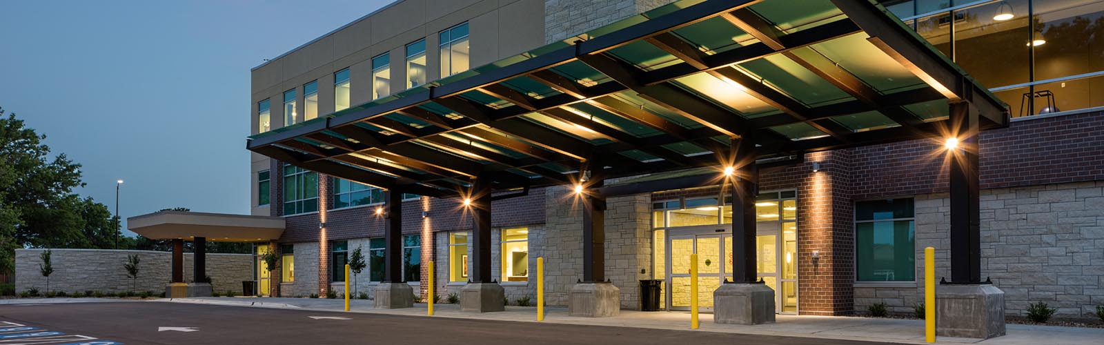
FINAL VIEW

While this tutorial seems to incorporate many steps – when you become familiar with them, it shouldn’t take more than a few minutes to produce nice, colored views with no rendering or waiting involved. These steps will work just as well for interior views as exterior views. You can also use the concepts behind them to produce colored, shaded elevations or just apply them to a standard working 3D view which you pan and zoom around to study your design/model.

I can print the view above just like any other view, in this case, I am going to print as a PDF on 11×17 paper. This is a piece of the actual image at that size for reference.
Article written by Byron Kurogi, a graduate architect with HMN Architects. He has been with the firm for just shy of ten years. In this time he has been an integral member of the team that has designed improvements and expansions to Stormont-Vail HealthCare, Hiawatha Community Hospital, and Lake Regional Health System. In the office he is considered the ‘unofficial’ 3D guru and Revit expert.
Posted on April 24, 2013
Category: HMN Services